
The Sound of Saturation
When power amplifiers suddenly finds itself having to deliver massive amounts of current, most will protect themselves by throttling back their output voltage.
On the better amplifiers, Safe Operating Area (SOA) circuitry kicks in.
On less well-designed units, the internal power supply voltages collapse, and the amplifier circuitry is simply unable to continue to deliver a faithful signal.
Some amplifiers may blow fuses or simply fail. The sound that you hear depends very much on how a particular amplifier responds to this type of overload.
Most likely, you will hear badly distorted bass and/or signal drop-outs.
Size Matters
As with most things audio, you need larger components to handle lower frequencies, and the same is true for transformers. If other design elements are held constant, the larger cores can tolerate higher primary voltage levels, because magnetic fields produce lower flux densities over their larger cross-sectional areas.
Another way to improve the voltage capability of a transformer is to increase the number of turns in each winding. However, unless the wire size is made smaller (resulting in higher resistive losses), the core may still have to be made larger to accommodate the additional turns of wire.
NOTE: Many of the distribution transformers we tested would have much improved performance if their designers had simply added a few turns of wire to their design.
Where Does It Say Saturation on the Datasheet?
Unfortunately, most transformer datasheets are not much help in providing specifications for low frequency performance. Some provide a vague ‘Frequency Response’ range. Our tests indicate that this is usually hopelessly optimistic if not dishonest: the power bandwidth at the low end is generally much lower than the specification.
Fortunately, since no secondary load is required to observe saturation, bench measurements are easy. Connect a sinewave source to the primary with a small-value resistor in series. Measure the rms voltage across the primary with a voltmeter or an oscilloscope.
Similarly measure the voltage across the resistor. Start at 1 kHz and sweep downwards. Across the resistor, you should measure a small voltage (proportional to primary current) that increases slowly as you decrease frequency.
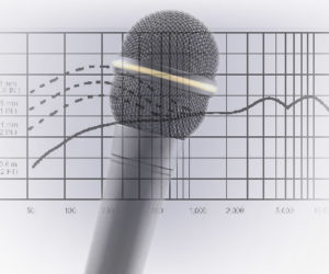
At some frequency, you will observe an abrupt increase in resistor voltage, indicative of the onset of saturation. Change the drive voltage and repeat the sweep. You should be able to derive a graph like the one shown here. This particular ‘300 watt’ transformer has a datasheet indicating “Frequency Response: 20 Hz to 20 kHz.” How would you rate it?

What About High Frequencies?
From the discussion about low frequencies and saturation, you have probably guessed that saturation is not a problem at high frequencies. However, other non-ideal characteristics come into play.
Stray magnetic fields, uncoupled between primary and secondary, show up as leakage inductance in series with the windings. Leakage inductance reduces the voltage available to the load at higher frequencies. Core losses are another phenomenon affecting high frequencies. The better cores use more expensive steels and thinner laminations.

Datasheet specifications are reasonably reliable indicators of high frequency performance.
Toroidal (at right in photo) types of transformers tend to have lower leakage inductance and better high frequency performance than most E-core models (at left in photo). However, excellent performance is available from either type of core: it all depends on the details of the design.